Deutsch
 English
 Español
 हिन्दी
 العربية
 Português do Brasil
 Русский
 日本語
 한국어
 Français
 Türkçe
 Polski
 Tiếng Việt
 Italiano
 简体中文
Metal Cutting describes the process where a cutting tool removes excess material from a workpiece surface to form chips and a finished surface. Chip formation brings cutting force, cutting heat, tool wear, plus practical shop issues such as built-up edge, scale-like burrs, chatter, chip curling and chip breaking. Operators often run into a common trouble: using the same tool, higher spindle speed causes material adhesion, larger feed triggers edge chipping, and ugly burrs or scale marks appear on finished surfaces. To solve these practical problems, we first need to understand that chips are not cut off sharply by the tool. They are squeezed out by the tool, and we need to see where deformation takes place.
Chip formation: shear slip as the core mechanism
A large number of tests prove the core rule. When the layer metal is pushed by the tool rake face, plastic deformation dominated by shear slip occurs. This resembles the compression failure test in material science, where the material slips along an approximate 45-degree plane. Continuous compression produces slip lines converging on both sides.
Three deformation zones with separate functions
Primary deformation zone · shear slip
Tertiary deformation zone · fiber structure and work hardening
Chip formation: shear slip as the core mechanism
We use the orthogonal free cutting model for easier analysis.
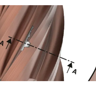
Common test methods to observe metal cutting deformation include grid pattern recording on the side of samples, high-speed filming, and quick-stop device tests. A quick-stop test locks the relative position of workpiece, tool and chip root the moment cutting happens. The sample is then made into a metallographic specimen for microscope observation. The metallographic photo of the chip root from quick-stop test shows clear deformation features: the side close to the tool rake face stays smooth, while the outer side looks fuzzy and fibrous.

Figure 1-1 Metallographic micrograph of chip root obtained by quick-stop test
A large number of tests prove the core rule. When the layer metal is pushed by the tool rake face, plastic deformation dominated by shear slip occurs. This resembles the compression failure test in material science, where the material slips along an approximate 45-degree plane. Continuous compression produces slip lines converging on both sides.
There is one key difference. In static compression tests, material can expand freely sideways. During Metal Cutting, the workpiece base below line DB restrains downward flow of metal. Shear slip only develops above DB and along line DA. Line DA is the shear slip line in cutting.

Figure2 Comparison between compression and metal cutting
Three deformation zones with separate functions
Many people think deformation only occurs right at the cutting edge. This is not true. The tool has a rake angle, and friction exists between tool and workpiece. After shear slip, chips keep flowing out along the rake face. The real process is far more complex than static compression tests. The industry widely divides the local cutting area into three connected, interacting deformation zones. These zones deform at the same time, with different core functions.

Figure3 Three deformation zones in cutting process
Primary deformation zone · shear slip
Point P in the cutting layer moves toward the cutting edge, and internal stress rises gradually. When it reaches the initial shear line OA, shear stress hits the yield strength of the material. The metal stops simple elastic compression and starts shear slip along OA.
As material keeps moving forward, shear strain accumulates continuously, grains stretch and twist. When the material reaches the terminal shear line OM, its flow direction turns parallel to the rake face, and shear slip stops.
The zone between OA and OM is the primary deformation zone, the main area of cutting deformation. Its key features are shear slip along slip lines and work hardening that follows. Most metal cutting force and cutting heat generate here. This zone directly decides whether chips come out continuous, serrated or fragmented.

Figure 4 Metal slip inside the primary deformation zone
Tertiary deformation zone · fiber structure and work hardening
Most operators focus on chips and overlook the area behind the cutting edge. The finished surface receives continuous extrusion and friction from the rounded cutting edge and tool flank face. After compression by the edge, metal bounces back elastically. The rebounded workpiece material rubs against the flank face again.
These actions stretch grains on the surface layer into fiber shapes and raise surface hardness, creating a work-hardened layer. This zone does not produce chips, but it directly controls surface roughness and residual stress. It is the main source of scale marks and surface scratches. It also raises risks of cracks in later finishing or grinding processes, and acts as the key factor deciding final surface quality.
Zusammenfassung
Understand the three deformation zones: the primary zone for shear slip that shapes chips and generates main cutting force and heat; the secondary zone for friction and extrusion that creates built-up edge and rake face wear; the tertiary zone for fiber formation and hardening that controls workpiece surface quality and hardened layer. When you look at built-up edge, scale marks, chip breaking and material adhesion with this foundation, you adjust cutting parameters based on clear logic instead of trial and error.