English
 Español
 हिन्दी
 العربية
 Português do Brasil
 Русский
 日本語
 Deutsch
 한국어
 Français
 Türkçe
 Polski
 Tiếng Việt
 Italiano
 简体中文
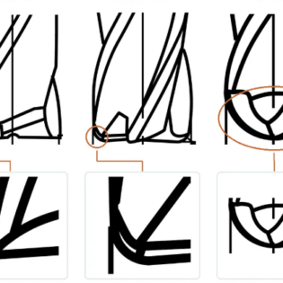
Uniform Flank Wear
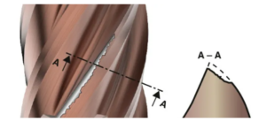
Uniform flank wear is a predictable and desirable wear pattern. However, excessively fast development of this wear still indicates abnormal machining conditions. It appears as a relatively uniform wear band along the cutting edge. Workpiece metal may make the wear band visually larger than its actual size. This type of wear occurs for all workpiece materials. If the tool does not fail from other wear modes in advance, gradual flank wear up to its limit represents the typical end‑of‑life condition for a cutting tool.
Solution: Increase coolant concentration appropriately, check the matching between feed rate and tool clearance angle, confirm the proper balance between cutting speed and feed rate, and select a tool suitable for the machined workpiece material.
Crater Wear on the Rake Face (including Pitting)
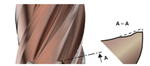
Solution: Balance feed rate and rake angle, verify the matching of cutting speed and feed rate, confirm whether the selected tool suits the workpiece material, raise coolant concentration, and reduce cutting speed and feed rate when necessary.
Micro‑chipping (including Local Edge Chipping)
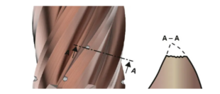
Micro‑chipping refers to partial fracture of the cutting edge, which is mostly caused by insufficient system rigidity and machining vibration. Local edge chipping is a special case of micro‑chipping. Apart from rigidity problems, it also emerges when chatter occurs due to improper milling strategies.
Solution: Keep tool overhang as short as possible, reinforce fixture setup to guarantee system rigidity, inspect tool run‑out to stay within specification limits, select a tool suitable for workpiece material and set correct cutting parameters, and ensure smooth chip evacuation. For local edge chipping, avoid chatter triggered by low cutting speed and adopt trochoidal milling when machining internal corners.
Built‑up Edge
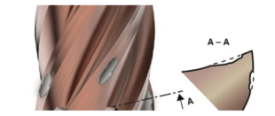
Built‑up edge forms when workpiece material adheres onto the rake face of an end‑mill. Pressure, friction and unsuitable cutting conditions lead to material deposition on the cutting‑edge surface.
Solution: Raise cutting speed appropriately, increase coolant flow rate and concentration, and select a proper end‑mill for the workpiece material by considering flute geometry, helix angle, coating and edge surface condition comprehensively.
Groove Wear

Groove wear means erosion of cemented‑carbide material within local zones of the cutting edge. In most situations, it originates from continuous friction between workpiece and cutting edge.
Solution: Re‑evaluate the geometric parameters of the end‑mill, change radial or axial cutting depth if process conditions permit, and lower cutting speed.
Chip‑evacuation Wear

Chip‑evacuation wear must not be confused with groove wear despite their similar appearance. Poor chip removal makes chips rub repeatedly against the cutting edge and generates damage on the end‑mill.
Solution: Reduce cutting depth moderately so that chips can be removed smoothly for double‑core tools, confirm that the tool matches the workpiece material, increase helix angle moderately, and decrease feed rate or cutting depth.
Step‑face Wear

Solution: Increase coolant flow, reduce feed rate or cutting speed, and select an end‑mill whose flute geometry fits the working condition.
Spalling

Spalling is the loss of thin fragments from the tool surface. It appears more frequently on coated tools. Thermal and mechanical stress initiates cracks inside the coating and further causes coating delamination. Sticky workpiece material and incorrect cutting parameters serve as major contributing factors.
Solution: Optimize cutting parameters, maintain stable machining conditions, improve cooling and lubrication performance, and decrease alternating stress acting on the coating.
Comb‑shaped Cracking

Comb‑shaped cracking consists of a series of comb‑like crack lines formed along the cutting edge or rake face. Milling belongs to interrupted cutting. Repeated heating and cooling cycles produce thermal shock and lead to this cracking.
Solution: Optimize cutting parameters to reduce heat generation, apply coated tools with better thermal resistance, enhance cooling and lubrication, avoid excessive cutting speed and feed rate, and choose cemented‑carbide substrates with superior thermal stability.
Non‑uniform Micro‑chipping

Non‑uniform micro‑chipping can appear at arbitrary points on the cutting edge. It usually starts from tiny cracks induced by mechanical or thermal stress. Interrupted cutting, machining vibration, weak fixture rigidity, hard spots on the workpiece and re‑cutting of formed chips create localized stress concentration, which results in irregular edge damage.
Solution: Improve tool clamping conditions to suppress vibration, optimize cutting parameters, strengthen cooling and lubrication, inspect the cutting edge regularly for early‑stage cracks, and pay attention to hardness variation of the workpiece material.
Catastrophic Fracture

Catastrophic fracture refers to complete breakage of the cutting tool. Mechanical overload, severe vibration, blocked chip evacuation, or neglected earlier minor wear modes can eventually lead to total tool breakage. If this failure takes place during high‑speed cutting, it not only destroys the tool, but also damages workpieces and machine tools, and brings potential safety hazards for machine operators.
Solution: Optimize fixture arrangement to suppress chatter and vibration, strictly check tool radial run‑out, limit tool overhang length, select tool holders with proper specification, adjust cutting parameters to lower the load acting on the cutting tool, and guarantee smooth chip evacuation during machining.