한국어
 English
 Español
 हिन्दी
 العربية
 Português do Brasil
 Русский
 日本語
 Deutsch
 Français
 Türkçe
 Polski
 Tiếng Việt
 Italiano
 简体中文
Aluminum alloy machining often comes with a widespread misconception: aluminum is soft and therefore easy‑to‑machine. Shops may grab cutting tools meant for steel and apply steel‑oriented cutting parameters, namely low spindle speed and low feed rate. This routinely leads to built‑up edge, tool adhesion, burrs and poor surface finish. Tool failure on steel is obvious through chipping, while built‑up edge on aluminum can progress silently without immediate detection.
In 2026, new‑energy vehicles use nearly 300 kilograms of aluminum alloy per unit. Battery trays, motor housings and large integrated die‑cast components are all aluminum parts. Aluminum alloy machining volume on production floors will keep growing. Proper tool selection and application for aluminum alloy machining has become essential knowledge for every machinist.
Aluminum alloy shows distinct cutting behaviour compared with steel, summarized in three points:
-
High ductility and strong chemical affinity cause cold welding. Aluminum alloy deforms plastically and produces continuous curled chips, unlike fragmented chips from cast iron or fractured chips from steel. Under high temperature and pressure during cutting, aluminum bonds readily with titanium found in cemented carbide substrates. Cold welding occurs on cutting edges and forms built‑up edge. Steel machining is challenged by material hardness, while aluminum alloy machining is mainly challenged by material adhesion.
-
High bulk thermal conductivity yet significant local thermal load at cutting edges. Aluminum alloy conducts heat far better than steel. However, continuous curled chips wrap around cutting edges and create friction. Local temperature can still reach aluminum’s melting point and weld work‑material onto tool edges. Good overall heat dissipation of the workpiece does not mean cool cutting edges.
-
Large thermal expansion coefficient leads to unstable dimensional performance. Aluminum alloy expands roughly twice as much as steel. Ambient temperature and heat generated in cutting both shift part dimensions. Some parts pass dimensional checks right after machining but fail inspection at customer sites due to thermal deformation. For finishing operations on aluminum alloy, avoid touching reference surfaces directly. Allow parts to cool fully before measurement, a basic quality‑control practice.
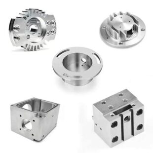
Built‑up Edge Formation
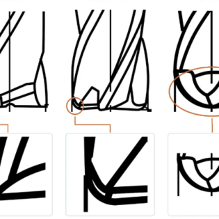
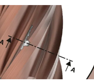
Most defects in aluminum alloy machining, including poor surface finish, heavy burrs, dimensional variation and premature edge damage, originate from built‑up edge. Under high temperature and pressure, aluminum material welds and accumulates on cutting edges. This alters the original tool geometry and creates an irregular effective cutting profile. On the shop floor, watch for dull cutting noise, hazy surface appearance and random depth‑varying scratches on workpieces. Stop the machine and inspect cutting edges for built‑up edge when these symptoms appear.
Aluminum alloy machining follows counter‑intuitive process logic: avoid low cutting speed; high cutting speed is preferred. Operators commonly reduce speed to protect tools in steel machining, but this logic does not apply to aluminum alloy. At low cutting speed, chip material cannot soften sufficiently, which creates favourable conditions for cold welding and built‑up edge. Field experience shows built‑up edge occurs frequently below 100 m/min. When cutting speed rises above 300 m/min, built‑up edge is greatly suppressed. If tool adhesion occurs, raise cutting speed and feed rate first instead of reducing parameters.
Coating Characteristics for Aluminum Alloy Machining Tools
Here is a key conclusion: TiN, TiCN and TiAlN, high‑performance coatings for steel, perform poorly for aluminum alloy. Driven by chemical affinity, aluminum reacts strongly with titanium under cutting heat. Titanium‑containing coatings accelerate chip adhesion and rapid built‑up edge growth. Investments in such coatings produce counter‑productive results for aluminum alloy work. Valid coating choices for aluminum alloy machining are listed below:
| Coating Option | Friction Performance | Application Scenarios | Plain‑language Note |
|---|---|---|---|
| Uncoated with mirror‑polished flute | Sharp cutting edge; polished flute surfaces resist material sticking | Finishing for pure aluminum, 6061, 6063 and other soft aluminum grades | Smooth surfaces minimize anchoring points for aluminum adhesion; top choice for soft aluminum |
| DLC diamond‑like carbon | Very low friction coefficient | High‑volume continuous cutting, die‑cast aluminum, high wear‑resistance requirements | Non‑stick coating; stable performance over long production runs |
| ZrN zirconium nitride | Titanium‑free with low friction | General‑purpose grade for aluminum and non‑ferrous metals | Practical option that eliminates titanium‑aluminum affinity risks |
This explains why most tool manufacturers maintain separate product lines for aluminum alloy machining and steel machining.

Impacts of Tooth Count, Helix Angle and Edge Preparation on Tool Adhesion
Tooth Count
End‑mill geometry for aluminum alloy differs from steel‑cutting end‑mills. Steel‑cutting tools often use 4‑flute or 6‑flute designs for rigidity. For aluminum alloy, 2‑flute tools are preferred, with 3‑flute as maximum acceptable option. The core consideration is chip room. Long sticky aluminum chips jam easily in narrow flutes of 4‑flute tools. Trapped chips undergo repeated compression and friction, raising heat and material adhesion. Two‑flute geometry provides large flute volume and supports fast chip evacuation.
Helix Angle
Large helix angle represents a critical parameter for aluminum alloy end‑mills. Steel‑cutting end‑mills generally stay below 40° helix angle. Aluminum alloy end‑mills commonly adopt 40°‑45° helix angle. Increased helix angle raises effective working rake angle, enables light‑cut shearing, improves chip curling and accelerates upward chip evacuation. Chip jamming and tool adhesion are reduced accordingly.
Edge Preparation
Edge preparation carries important practical details. Aluminum alloy end‑mills require controlled micro‑honing within 0.02‑0.05 mm. Sharp unhoned edges develop micro‑chipping under cutting load. These micro‑defects become starting points for aluminum material adhesion. Micro‑honing preserves nearly full sharpness while greatly improving resistance against micro‑chipping. Reputable aluminum‑tool manufacturers implement this process. The difference is barely visible to naked eyes but delivers noticeable performance improvements in actual cutting.

Turning Insert Selection for Aluminum Alloy
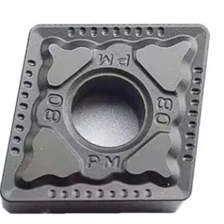
Select ISO group N inserts dedicated to non‑ferrous metals for aluminum alloy turning. Do not substitute group P inserts for steel or group M inserts for stainless steel. Most manufacturers mark aluminum‑focused inserts with AL‑designated chip‑breaker geometries. Key features include large positive rake angle around 20° and mirror‑polished rake faces. The hone‑land commonly used on steel inserts is generally omitted to preserve sharp shearing action.
Follow the principle: prioritize higher cutting speed. Cemented carbide inserts for 6061 aluminum alloy can run at several hundred meters per minute. Finishing operations can reach 400‑600 m/min. Operating near 100 m/min creates conditions favourable for built‑up edge. When surface quality degrades and random scratches appear during turning, increase cutting speed before considering tool replacement.
Nose radius selection: 0.4 mm nose radius works for general finishing. For thin‑walled and slender aluminum alloy parts, reduce nose radius to 0.2 mm. Lower radial cutting force minimizes workpiece deflection. For thin‑walled components, workpiece stability takes priority over pure tool service life.
Machining Properties of Different Aluminum Alloy Grades
Simply referencing “aluminum alloy” provides insufficient information for process setup. Machining behaviour varies widely across grades. Confirm material grade before tool selection.
| 등급 | Material Behaviour | Machining Notes | Recommended Tool Solution |
|---|---|---|---|
| 1050 pure aluminum / 5‑series | Very soft, high adhesion tendency, low melting point | High risk of built‑up edge; sufficient cutting speed and lubrication required | Uncoated mirror‑polished tools with maximum sharpness |
| 6061 / 6063 | Balanced general‑purpose alloy | Wide process tolerance; avoid improper parameter settings | 2‑flute / 3‑flute high‑helix tools, uncoated or ZrN coated |
| 7075 / 2024 | High strength comparable to steel | Chips fracture well for good finish yet accelerate tool wear; 2024 produces heavy burrs | Sharp aluminum‑specific tools; reduce speed by 10 %; plan for post‑deburring |
| High‑silicon die‑cast aluminum (Si>8%) | Silicon particles act as abrasive media | Cemented carbide edges wear rapidly within dozens of minutes; surface quality collapses quickly | PCD inserts as the primary practical solution |
Note: When silicon mass fraction exceeds 8 %, PCD tools shift from optional to mandatory.

Recommendations for Tool Distributors
-
Maintain separate product lines for aluminum alloy machining tools and steel‑cutting tools, with physical separation in storage. Most field failures stem from using titanium‑coated steel‑cutting tools on aluminum alloy, leading to scrapped parts and premature tool wear, with customers blaming tool quality. Mark aluminum‑focused tools clearly: “Uncoated / DLC / ZrN. Not for steel machining”. Explain coating compatibility logic to end‑users in advance to reduce risk and build customer confidence.
-
“Machining aluminum alloy” alone offers insufficient information for tool recommendation. Confirm exact material grade as part of technical service. Customers recognize proposals tailored to their actual work conditions instead of generic stock‑driven suggestions.
-
New‑energy vehicles keep raising aluminum consumption. Build technical know‑how for aluminum alloy machining tools and establish trust with component manufacturers. This supports consistent tool supply opportunities through mass‑production phases.