Polski
 English
 Español
 हिन्दी
 العربية
 Português do Brasil
 Русский
 日本語
 Deutsch
 한국어
 Français
 Türkçe
 Tiếng Việt
 Italiano
 简体中文
Chip‑breaker is a critical geometric feature on cutting inserts that directly controls chip formation during metal‑cutting operations. In metal‑cutting workshops, tool selection generally refers to the P, M and K material classifications specified in ISO 513. The prevailing understanding among shop‑floor workers is that P corresponds to steel, M to stainless steel, and K to cast iron. However, most practitioners only retain this simple matching rule. They do not realise that this classification was originally defined according to cutting conditions and chip characteristics, and they ignore its close relationship with insert profiles and chip‑breaker design. Starting from fundamental machining properties of workpiece materials, this paper gives a straightforward explanation of the true definition and naming origin of P, M and K, as well as the design logic of insert chip‑breakers for different materials, so that tool selection no longer depends merely on practical experience.
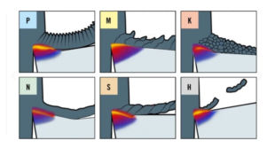
Characteristics of Three Basic Work‑material Classifications
The industrial application of cemented carbide originated in Germany. In 1923, Krupp formally registered the Widia brand for cemented carbide, laying the foundation for modern cemented‑carbide cutting‑tool development. The three major tool classification codes P, M and K under ISO 513 also derive from German definitions of chip formation.
Category‑P Workpiece Materials
The code P comes from the German word Plastisch, meaning ductile and extendable. Typical machining objects include carbon steel and alloy steel. These metals possess high toughness and good ductility. They are not prone to brittle fracture during cutting and sustain continuous plastic deformation, forming long, continuous ribbon‑shaped chips. This represents the typical ductile cutting state.
Category‑M Workpiece Materials
The code M originates from the German word Misch, which means mixed or intermediate state. It is designated for austenitic stainless steel, high‑manganese steel and other difficult‑to‑machine alloys. Stainless steel has distinctive cutting behaviour. It does not steadily produce long chips like carbon steel, nor does it break into instant fragments like cast iron. Its performance and chip morphology fall between Category‑P steel and Category‑K cast iron. In addition, stainless steel is susceptible to work‑hardening and built‑up‑edge formation, which leads to unstable cutting conditions; therefore it is defined as a mixed‑condition workpiece material.
Category‑K Workpiece Materials
The code K is derived from the German term Kurzspanend, referring to short‑chip behaviour. It is mainly suitable for brittle materials such as cast iron. These materials exhibit very low ductility and barely undergo plastic elongation. The material fractures and flakes off instantly under tool cutting, producing fine, powdery or granular chips. Chip fragmentation happens spontaneously without assistance from curled structures on the cutting insert.
Newly‑added Category‑N, S and H Workpiece Materials
With the continuous advancement of modern manufacturing, a growing number of new difficult‑to‑machine materials have emerged. The original three categories can no longer cover all machining conditions. For this reason, the ISO standard later introduced three supplementary material categories: N, S and H. Unlike the traditional German‑oriented naming system, these new designations adapt to both German and English definitions for wider applicability. Category‑N stands for non‑ferrous metals, following the relevant definitions in German and English. It covers aluminium alloys, copper alloys, plastics and other low‑hardness non‑metallic and light‑metal materials that tend to adhere to cutting edges. Category‑S denotes special high‑temperature alloys, including titanium alloys and nickel‑based superalloys widely used in the aerospace sector. Category‑H represents hard materials, mainly quenched steel and chilled cast iron above HRC45 for ultra‑hard cutting applications.
Influence of Work‑material Properties on Chip‑breaker Design
Category‑P Chip‑breaker
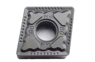
When machining ductile Category‑P materials such as carbon steel and alloy steel, long continuous chips are easily generated. These chips tend to wrap around workpieces and cutting tools and impair machining stability. Accordingly, Category‑P inserts are made with deep chip pockets and raised obstruction walls on the rake face. In the cutting process, long chips flow along the rake face into the chip‑breaker and are forced to curl. The bending radius keeps changing until internal bending stress exceeds the fracture limit of the workpiece material, and the long chip breaks to realise controlled chip breaking. In terms of design trade‑offs, deeper chip pockets and steeper obstruction walls deliver stronger chip‑breaking performance. Nevertheless, they also increase cutting contact resistance and cutting temperature, which imposes stricter requirements on matching cutting parameters.
Category‑K Chip‑breaker
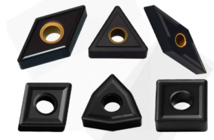
For brittle Category‑K materials such as cast iron, short fragmented chips break away spontaneously. Most Category‑K inserts therefore adopt flat rake‑face layouts without chip‑breaker grooves. Common insert styles include CNMA and WNMA. Removing complicated chip‑breaker structures preserves the maximum cross‑sectional area for the cutting edge, improving substrate strength and impact resistance of the tool. Cast iron contains numerous hard inclusions that trigger frequent cutting shocks. The solid flat cutting edge resists particle‑induced impacts, reduces micro‑chipping and flank wear, and ensures stable mass‑production machining.
Category‑M Chip‑breaker

Machining Category‑M materials such as stainless steel frequently results in built‑up‑edge formation, work‑hardening and high‑temperature adhesion. Conventional chip breaking through impact against obstruction walls aggravates material adhesion and seriously damages workpiece surface quality. Hence, Category‑M chip‑breakers adopt insert geometry with large rake angles and sharp cutting edges. This design abandons chip breaking by violent squeezing and impact and completes material removal through smooth shearing. It reduces cutting‑deformation resistance and heat accumulation, restrains built‑up‑edge and notch wear, and addresses typical machining problems of stainless steel related to adhesion and work‑hardening.
Category‑N Chip‑breaker
Aluminium alloys, copper alloys and other Category‑N non‑ferrous metals are soft with high ductility and low friction coefficients. Extremely long continuous chips form during cutting, and material adhesion readily scratches the machined workpiece surface. Dedicated Category‑N inserts therefore feature large rake angles, shallow grooves and smooth curved surfaces. The chip‑breaker cavity is wide and smooth without sharp raised obstruction ridges. Lower cutting resistance minimises plastic squeezing of workpiece material. Unobstructed chip flow prevents chip deposition and sticking on cutting edges. The smooth rake‑face surface suppresses built‑up‑edge formation, achieves good surface finish for non‑ferrous metals, and suits precision finishing and high‑speed‑cutting operations.
Category‑S Chip‑breaker
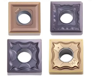
Category‑S difficult‑to‑machine materials such as titanium alloys and nickel‑based superalloys demonstrate poor thermal conductivity, severe work‑hardening and concentrated cutting stress. The cutting edge endures heavy shock loading, yet forced chip curling for chip breaking must be avoided. Category‑S chip‑breakers adopt dedicated geometry with wide chip cavities, gentle curved surfaces and lightly reinforced cutting edges. Sufficient space inside the chip cavity prevents excessive chip bending and secondary work‑hardening of the workpiece. Gentle curved surfaces disperse cutting stress and localised high temperature. Lightly honed cutting edges retain acceptable sharpness while improving resistance against chipping. This geometry adapts to low‑speed, heavy‑load cutting conditions for superalloys and titanium alloys prone to work‑hardening.
Category‑H Chip‑breaker
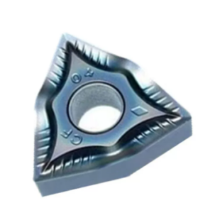
For Category‑H hard workpieces such as quenched steel and hard cast iron with hardness above HRC45, material removal occurs mainly via abrasion and extrusion‑driven separation. The cutting edge withstands extreme pressure and abrasive wear. Category‑H inserts eliminate large‑curvature chip‑breaker structures and adopt lightly grooved or fully flat reinforced cutting‑edge profiles with robust geometry. Reduced rake angles strengthen cutting‑edge integrity to resist continuous abrasive wear and impact loads from hard workpieces. These inserts are not optimised for light cutting. Their primary objective is to enhance edge rigidity, thermal resistance and wear resistance, avoid edge chipping and catastrophic fracture, and sustain stable machining for hard workpieces.
Wniosek
A chip‑breaker is not an isolated geometric feature; instead, it represents a targeted geometric solution developed according to chip characteristics of workpiece materials. In actual production, tool selection should not be carried out merely by matching insert grades against workpiece material designations. Operators ought to understand cutting‑mechanics principles behind the P‑M‑K‑N‑S‑H classification. When chip‑breaker profiles are properly selected for on‑site working conditions, chip formation can be better controlled, the risk of cutting‑edge chipping can be lowered, tool service life can be extended, and overall machining stability can be improved.