For CNC machine tools (machining centers) and other automated machining equipment, the issue of chip breaking becomes even more critical due to the larger number of tools and their close interaction with the tool holder. If even one tool has unreliable chip breaking, it could disrupt the machine’s automatic cycle and, in some cases, halt the entire production line. Therefore, when designing, selecting, or grinding tools, the reliability of chip breaking must be taken into consideration. Specifically for CNC machine tools (machining centers), the following requirements should be met:
- Chips must not wrap around the tool, workpiece, or adjacent tools and equipment.
- Chips must not splatter to ensure the safety of operators and observers.
- During precision machining, chips must not scratch the already processed surfaces of the workpiece, affecting the quality of those surfaces.
- Ensuring the intended durability of the tool, avoiding premature wear, and preventing tool breakage as much as possible.
- When chips flow out, they should not obstruct the delivery of cutting fluid.
- Chips should not damage machine tool guides or other components.

Classification of Chip Shapes
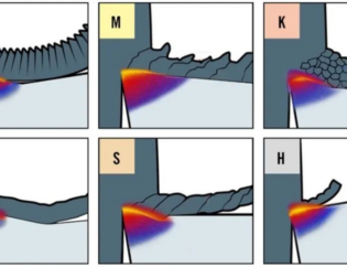
The shape of chips produced in machining varies depending on factors such as workpiece material, tool geometry, and cutting parameters. Common chip shapes include ribbon chips, C-shaped chips, fragmented chips, pagoda-shaped curled chips, spring-shaped curled chips, long, tight spiral chips, and spiral chips (see Figure 1).
Ribbon Chips
When machining ductile materials at high speeds, continuous ribbon chips can form easily. These chips can become entangled around the workpiece or tool, potentially scratching the workpiece surface, damaging the cutting edge of the tool, or even causing injury. Thus, it’s generally best to avoid forming ribbon chips. However, there may be situations where ribbon chips are desired to facilitate chip removal, such as when boring blind holes on a vertical boring mill.
C-Shaped Chips
When turning general carbon steel or alloy steel materials and using cutting tools with chip breakers, C-shaped chips can form. C-shaped chips don’t have the disadvantages of ribbon chips. However, most C-shaped chips are prone to impact the back surface of the cutting tool or the workpiece, causing them to break (see Figure 2). The high-frequency breaking and fracturing of chips can affect the smoothness of the cutting process and, subsequently, the surface roughness of the finished part. Therefore, in precision machining, it’s generally not desired to produce C-shaped chips, but instead, longer spiral chips (see Figure 3) are preferred to maintain a smoother cutting process.
Spring-Shaped Curled Chips
When heavy cuts and large feed rates are used to turn steel parts on a heavy-duty lathe, wide and thick chips are produced. Forming C-shaped chips in this scenario can easily damage the cutting edge and even pose an injury risk. To prevent this, the radius of the chip breaker’s groove bottom is increased to create spring-shaped chips (see Figure 4). These chips collide and break on the machining surface, falling under their weight.
Spiral Chips
The formation of long, tight spiral chips is a smoother process, and they are easy to clean up. This chip shape is favored for use on regular lathes.
Pagoda-Shaped Curled Chips
When CNC machining or using automated machinery, it’s preferable to produce this chip shape because it doesn’t wrap around the cutting tool or workpiece, making it easier to clean up.
Fragmented Chips
When turning brittle materials like cast iron, brittle brass, or phosphor bronze, needle-like or fragmented chips can easily form. These chips are prone to splattering and causing injuries, as well as damaging the machine tool. Using chip-breaking methods can turn these chips into short, curled chips.
In conclusion, the desired chip shape in cutting operations varies based on specific conditions. Regardless of the chip shape, it’s essential for chip breaking to be reliable.
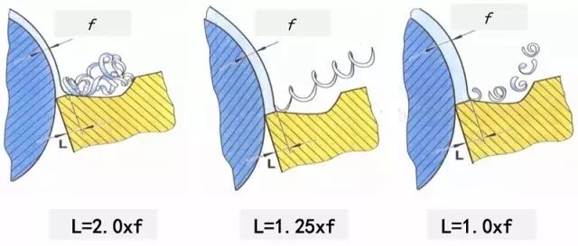
Mechanism of Chip Breakage
Whether metal chips are prone to breaking during metal cutting is directly related to the deformation of chips. To understand the principles of chip breakage, one must first examine the deformation patterns of chips.
During metal cutting, chips undergo significant plastic deformation. This process leads to an increase in chip hardness but a significant decrease in plasticity and toughness. This phenomenon is known as strain hardening. After strain hardening, the chips become hard and brittle, making them prone to breaking when subjected to alternating bending or impact loads.
The degree of plastic deformation that chips undergo affects the extent of their strain hardening and susceptibility to breaking. In cases where high-strength, high-plasticity, and high-toughness materials are being machined, measures must be taken to increase chip deformation, thereby reducing their plasticity and toughness to facilitate chip breaking.
Chip deformation can be divided into two components:
Basic Deformation: This is the deformation that occurs during the cutting process and is close to the values of basic deformation measured when free-cutting with a flat-fronted tool. The primary factors affecting basic deformation are the tool’s front clearance angle, negative rake angle, and cutting speed. A smaller front clearance angle, wider negative rake, and lower cutting speed result in greater chip deformation, which is favorable for chip breaking. Therefore, reducing the front clearance angle, increasing the negative rake angle, and decreasing the cutting speed can promote chip breaking.
Additional Deformation: In most cases, basic deformation alone cannot result in chip breaking. Additional deformation is required to harden and break the chips. The simplest method to subject chips to additional deformation is to grind (or press) chip-breaking grooves on the tool’s front surface. When chips flow into these grooves, they experience additional bending and coiling deformation, leading to further hardening and brittleness. This makes the chips easily break upon contact with the workpiece or the tool’s back surface.
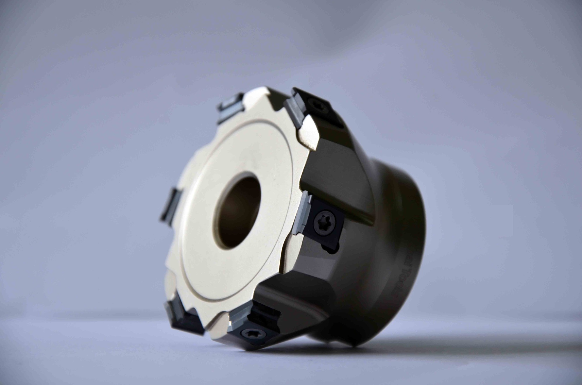
Common Chip Breaking Methods
Using Chip-Breaking Grooves
Chip-breaking grooves are effective in achieving both basic and additional deformation. The shape, size, and angle of the grooves play a crucial role in chip breaking.
Using Chip Breakers
Chip breakers can be fixed or adjustable and are effective in controlling chip curling and breaking. They are often used on medium and large-sized machine tools.
Using Chip-Breaking Devices
These devices come in mechanical, hydraulic, and electrical forms, are reliable, but typically cost more. They are commonly used in automated production lines.
Using Pre-Grooved Workpiece Surfaces
Grooves are pre-cut on the workpiece surface parallel to its axis. These grooves, which are slightly shallower than the cutting depth, create weaker sections in the chip, facilitating chip breaking. This method can be particularly useful for machining tough materials.
In summary, achieving chip breaking depends on the material and cutting conditions. Various methods, including adjusting tool geometry, modifying cutting parameters, and using chip-breaking devices, can be employed to promote reliable chip breaking. Chip breaking is essential for safety and efficient metal cutting processes.
